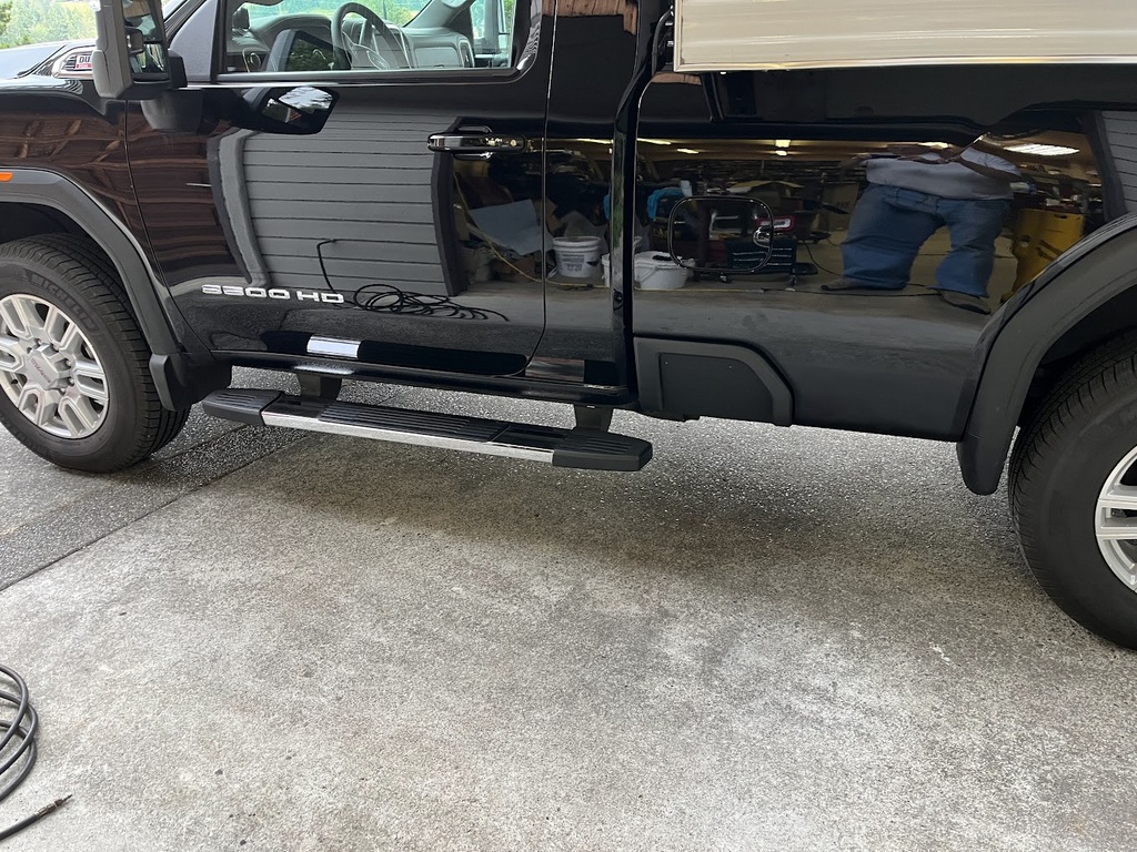
2022 Sierra 3500HD
Grille and Hood Molding Replacement
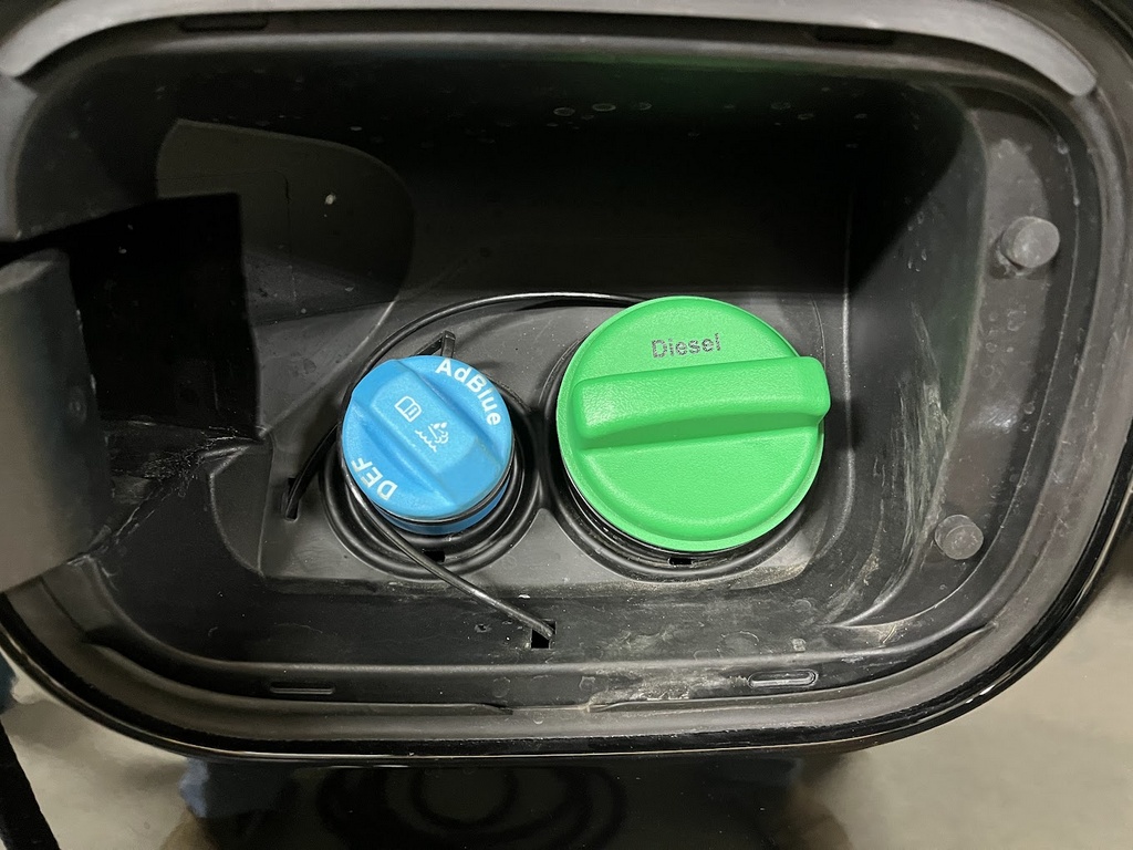
and Adding an Auxiliary Fuel Tank
(updated 9/23/23)
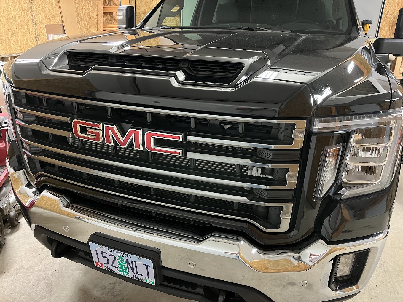
My new 2022 Sierra 3500 HD is a great truck. But the front has a bit too much chrome for my taste.
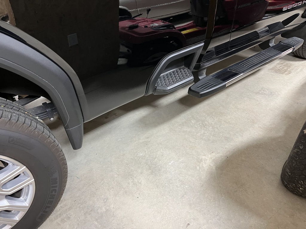
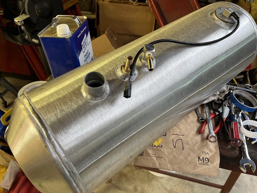
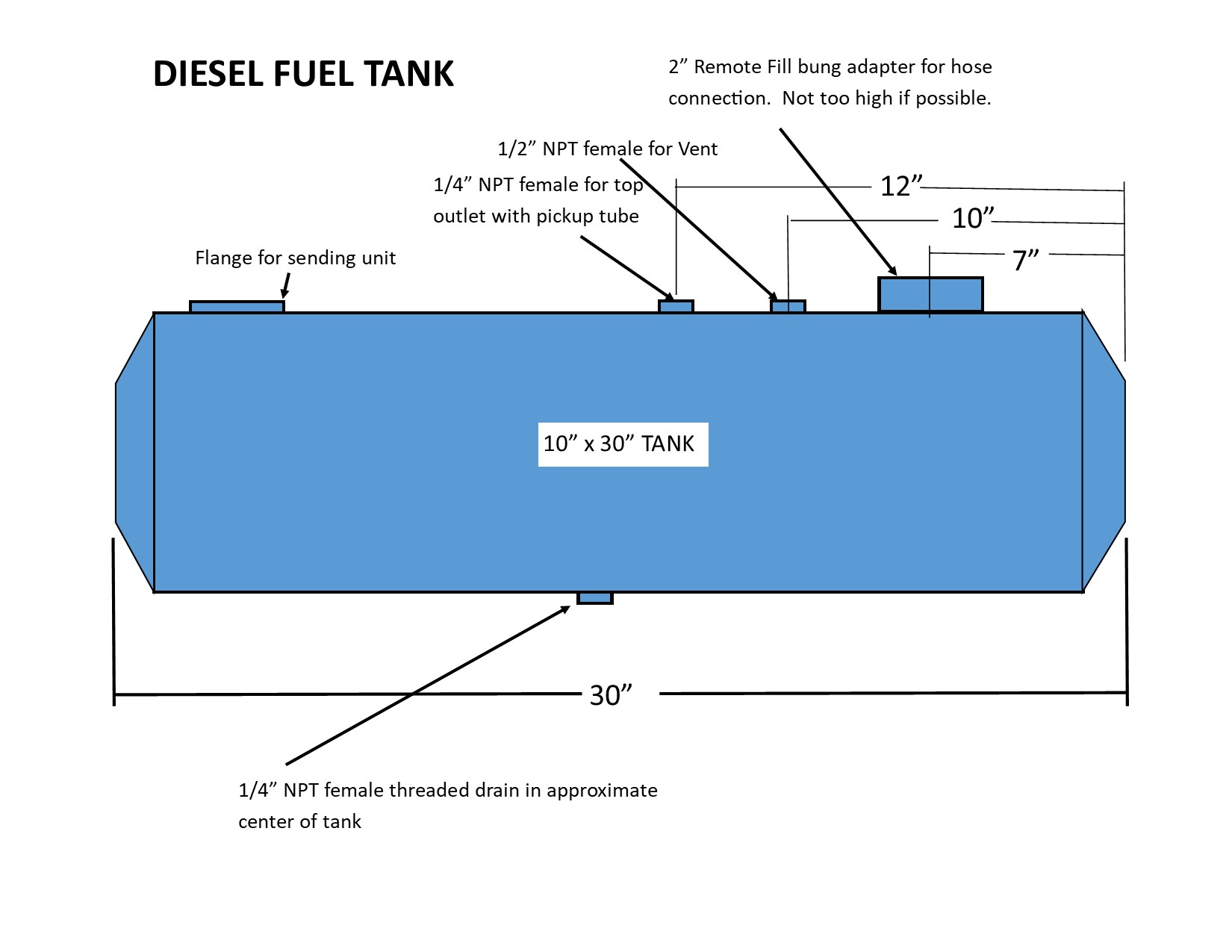
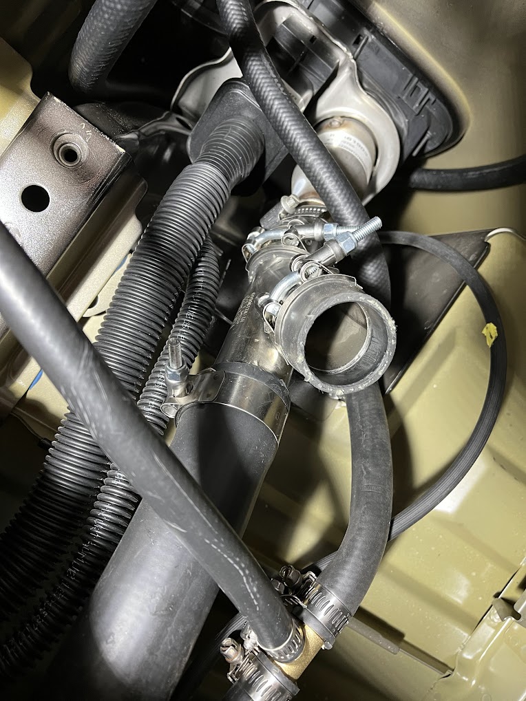
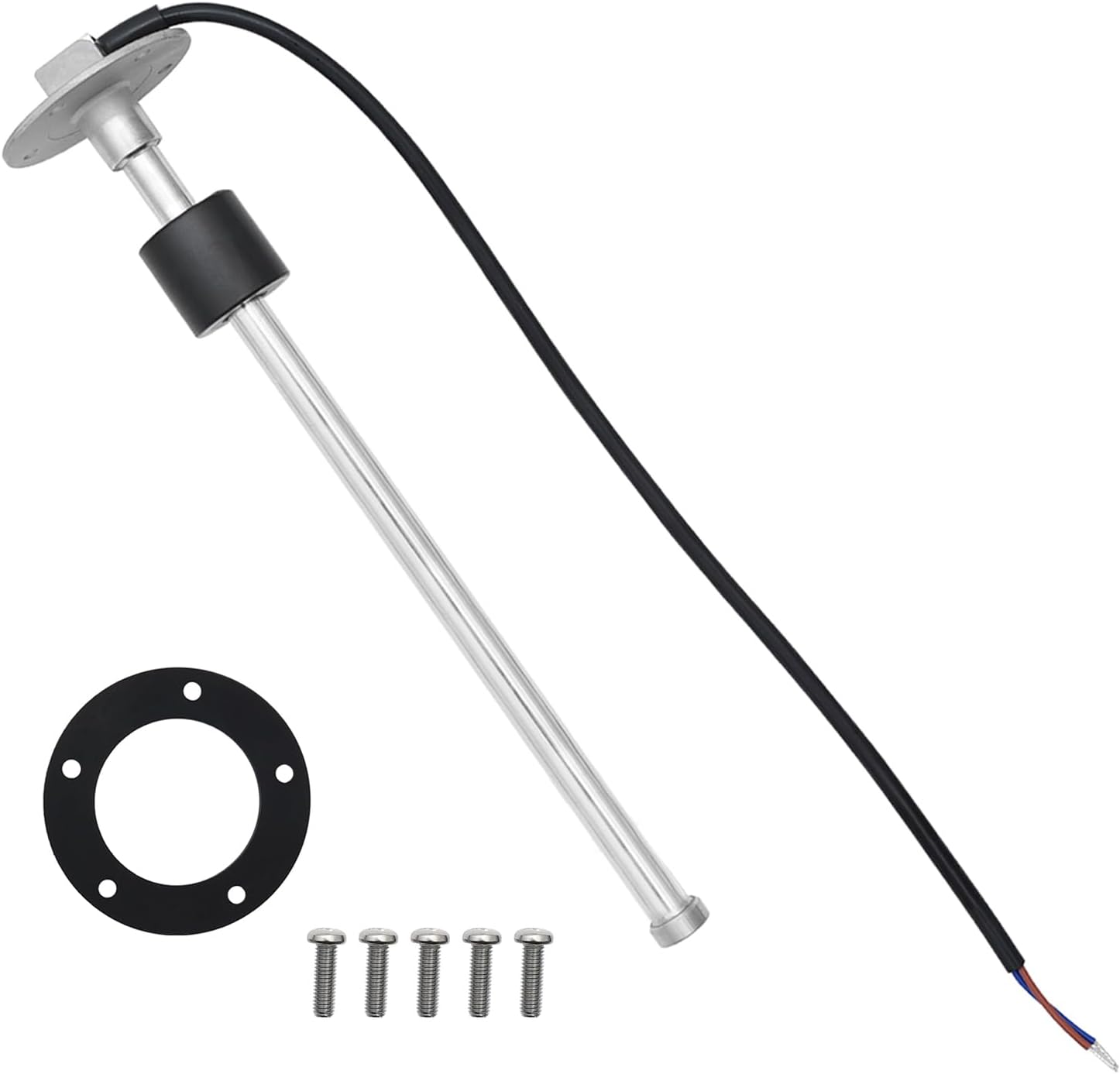
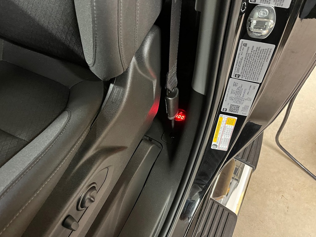
and my 26 gallon fuel tank is smaller than I'd like.
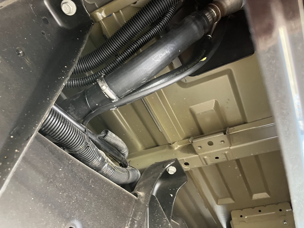
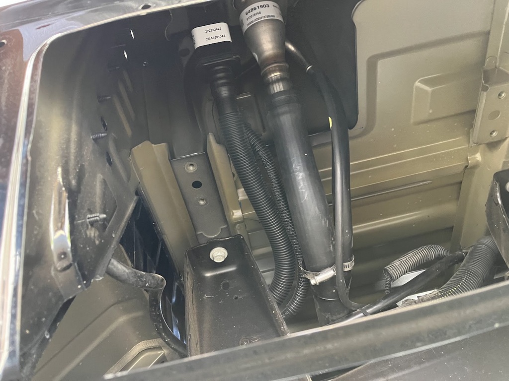
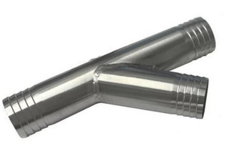
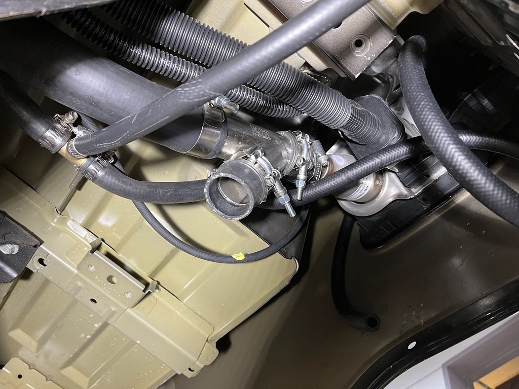
So for extra fuel capacity, I added another 10 gallons:
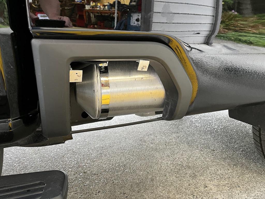
Click HERE for the fuel tank installation. Or continue on for the new grille installation:
For the new grille, I ordered one from a Sierra AT4. The GM part number is 84865572 and it includes the black front hood molding (GM part number 84774164).
The original chrome hood molding is part number 84774163.
Here's a photo of the truck with the new black hood molding but the original grille and the new AT4 grille below it:
The AT4 grille has black light surrounds and black chrome in front.
There are quite a few YouTube videos about how to replace both the hood molding and the grille, but they are not complete and some are incorrect.
If you buy this replacement grille, there are no instructions and it isn't clear what you need to do to install them. So this web page will provide the details.
First, let's tackle the front hood molding.
The molding is fastened to the hood with three special screws, two 7mm screws, and nine clips. But to remove the hood molding you must first remove the hood air vent.
This is because two 7mm screws are inaccessible until the air vent is out of the way.
Here's a photo of the hood with both the air vent and the hood molding removed:
So, in order to get to the hood molding, we need to first remove the air vent.
Removing the Air Vent
The Air Vent is fastened to the hood with four special screws with 8mm nuts and eleven clips.
Here's the Air Vent:
And here is the underside of it:
Note on the left side of the photo above, two of the four special screws. The other identical screws are on the other end of the vent.
One of the screws in the photo is short and the other is VERY long. Both of these screws go through the hood and are fastened with 8mm nuts.
The long screw is so long that a deep socket won't reach the nut. So I had to fabricate a long socket like this:
The long screw goes all the way through the 8mm socket in into the 11mm socket so it will reach the nut. The duct tape is adequate to loosen and tighten the nuts.
The short screw nuts can be easily reached with a normal 8mm socket.
So open the hood to find where the screws and nuts are located.
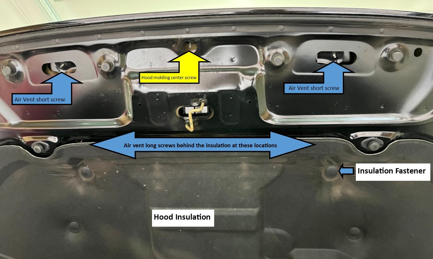
In the center of the above photo is one of the three special screws for the Hood Front Molding (yellow arrow).
The photo below shows one of the end Hood Molding special screws:
The third special screw is at the other end of the molding and hood.
Using an 8mm deep socket, remove the three special Hood Molding nuts, being careful not to drop the nuts.
Also remove the two 8mm nuts from the short Air Vent special screws.
To gain access to the two very long Air Vent special screws to need to drop the Hood Insulation.
Pry the four Insulation fasteners loose that are near the big blue arrow in the first photo above.
Pull down the insulation to find the screws
Try not to bend the insulation too much:
Using the home made tool shown above, reach way in to loosen the 8mm nuts on these very long screws.
With the four nuts removed from the Air Vent and the three nuts removed from the Hood Molding, the only fasteners left on the Air Vent are the clips.
Using a plastic pry tool and/or your fingers, pry up on the Air Vent at the front to break the clips loose. See the photos above to understand what the clips look like.
Hopefully they won't break as you pry them up - one of mine did and new ones (GM part number 11610700) are hard to find.
Removing the front Hood Molding
Once the Air Vent is removed, you will see the two 7mm screws still holding the Hood Molding in place:
The above photo shows the new black Hood Molding already installed. The original chrome molding is identical.
Here are a couple of photos to show the clips on the underside of the Hood Molding:
Once the two 7mm screws are removed, and the three nuts from the special screws are removed, only the nine clips hold the Hood Molding in place.
Using a plastic pry tools and/or your fingers, pry the Hood Molding off of the hood.
Installation of the new Hood Molding is just the reverse - very simple but make sure all of the clips came off with the original molding.
Removing the Grille
The YouTube videos I saw showing how to remove the grille all said the Underlight Corner Molding needed to be removed.
This isn't easy and I wasted about an hour struggling with it, until I finally realized it isn't even necessary.
The lower part of the grille protrudes behind these moldings, but they are flexible and I found that once the one clip under the light is pulled free, the molding will bend enough to allow the grille to be removed.
Just grab the molding at the bottom, under the light, and pull forward and a little bit outward. The clip (GM part number 11547581) will pull loose from a hole and the molding will bend.
Leave all of the sides of the molding in place near the fender opening. There is a 7mm screw back behind the wheel well molding that holds the underlight corner molding in place, but the corner molding doesn't need to be removed.
Here's the new AT4 Grille:
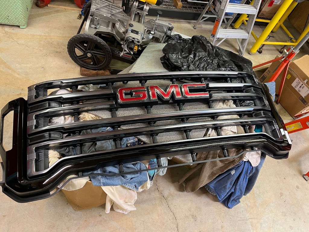
And here's the back of the grille:
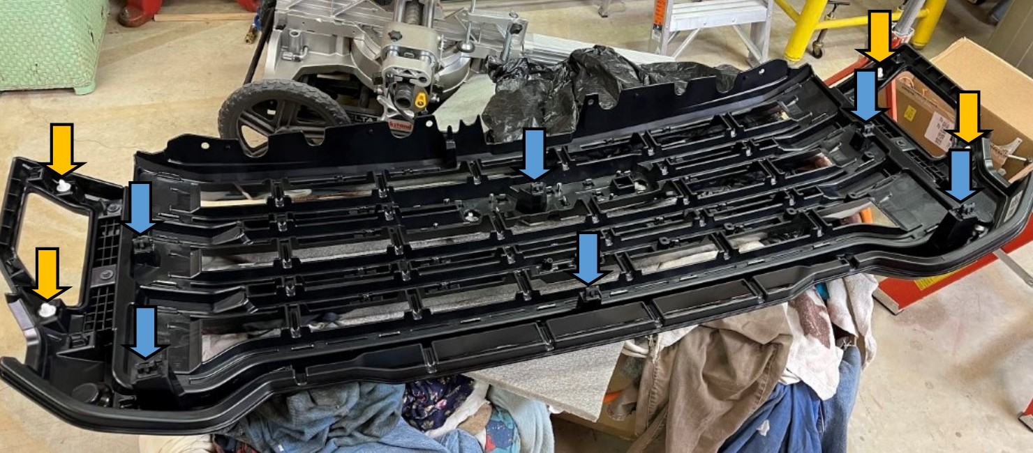
The grille is held in place by four 10mm bolts and the ten clips shown above.
The "blue" clips do most of the holding and the "yellow" clips hold the light surrounds in place.
Removal and installation is quite simple.
Open the hood and this is your view:
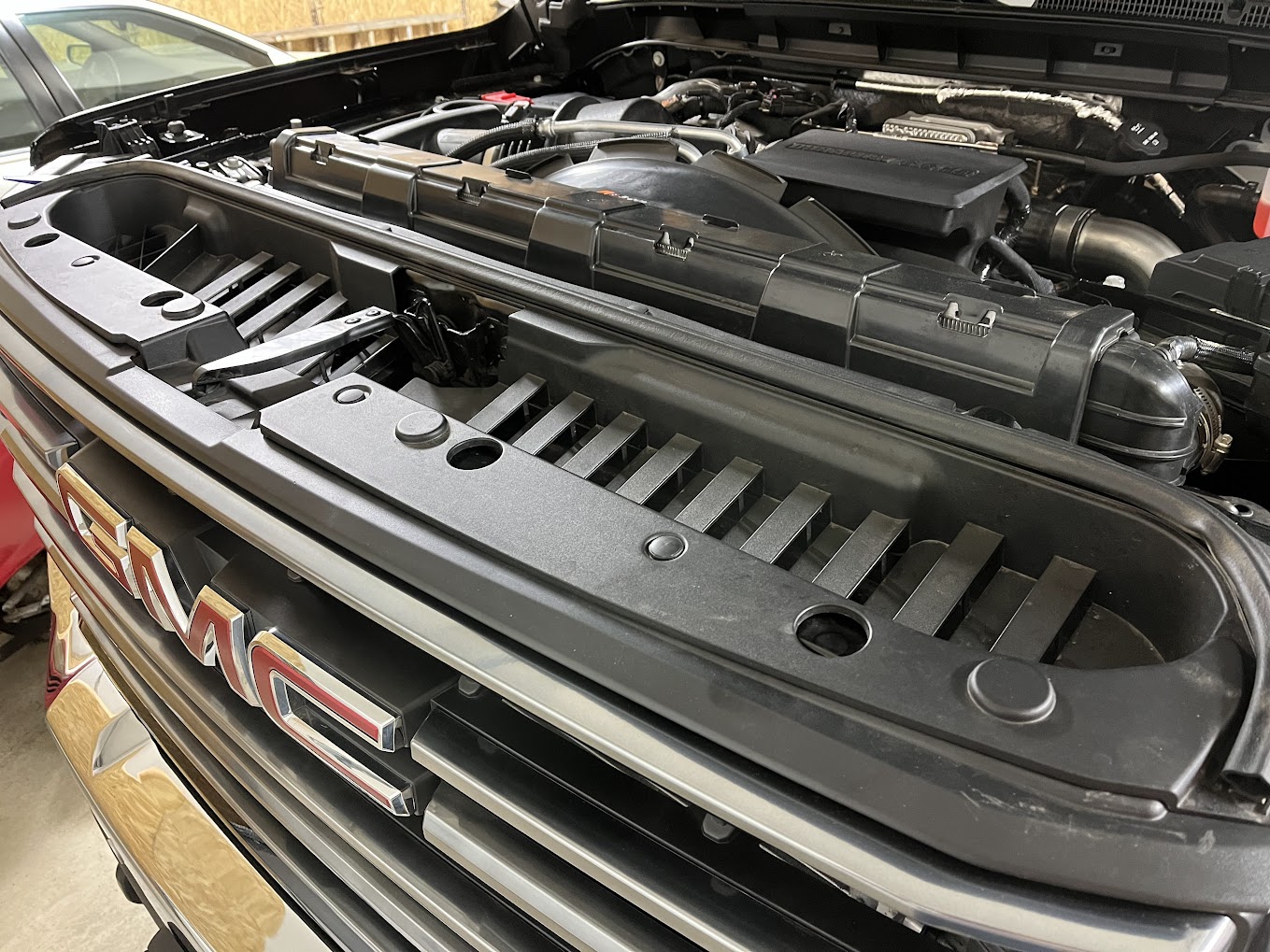
You need to remove this plastic cover between the grille and the radiator, which is very simple.
First remove the hood latch lever with a #15 Torx screwdriver:
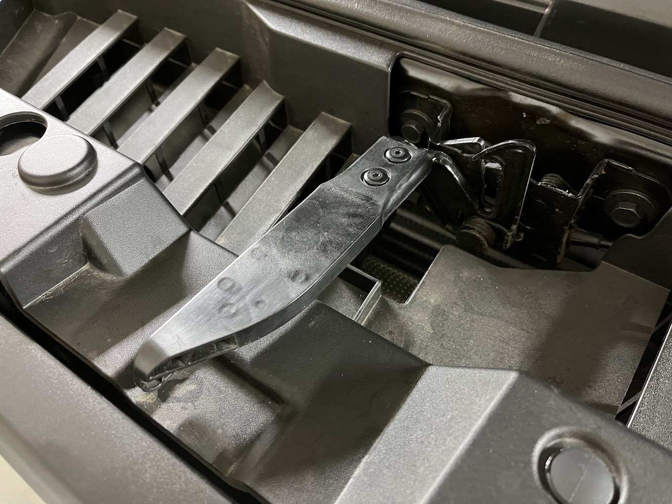
Then pull out the plastic rivets holding the plastic radiator cover in place. Three are shown in this photo:
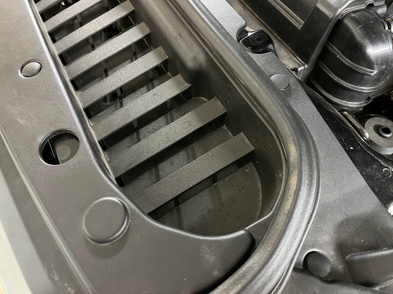
Using a small screwdriver or pry tool, first pull up on the top part of the rivet to release the bottom part. Then pull out each bottom section of the rivet.
Once all the rivets are out and the hood latch is removed, the plastic cover will easily pull out.
You will now see four 10mm bolts holding the grille to the frame. Remove each of them.
Pull the grille forward, which will release all of the upper clips holding the grille in place. (See photo above with the blue and yellow arrows.)
At this point, if you could pull out the remaining bottom "blue" and "yellow" marked clips, the grille would come right out.
But the lower part of the grille protrudes behind the flexible plastic corner moldings below the lights, so it won't come out straight towards the front.
Grab each of the moldings (one at a time) at the bottom and pull forward at a bit of a side angle.
The front molding clip will release, allowing you to flex the molding out and away from the grille.
You can now pull the grille forward at the bottom to release any remaining clips.
Once all the clips are disconnected, you can pull the grille sideways to clear one molding, then the other way to clear the other one.
Here's a photo with the grille removed:
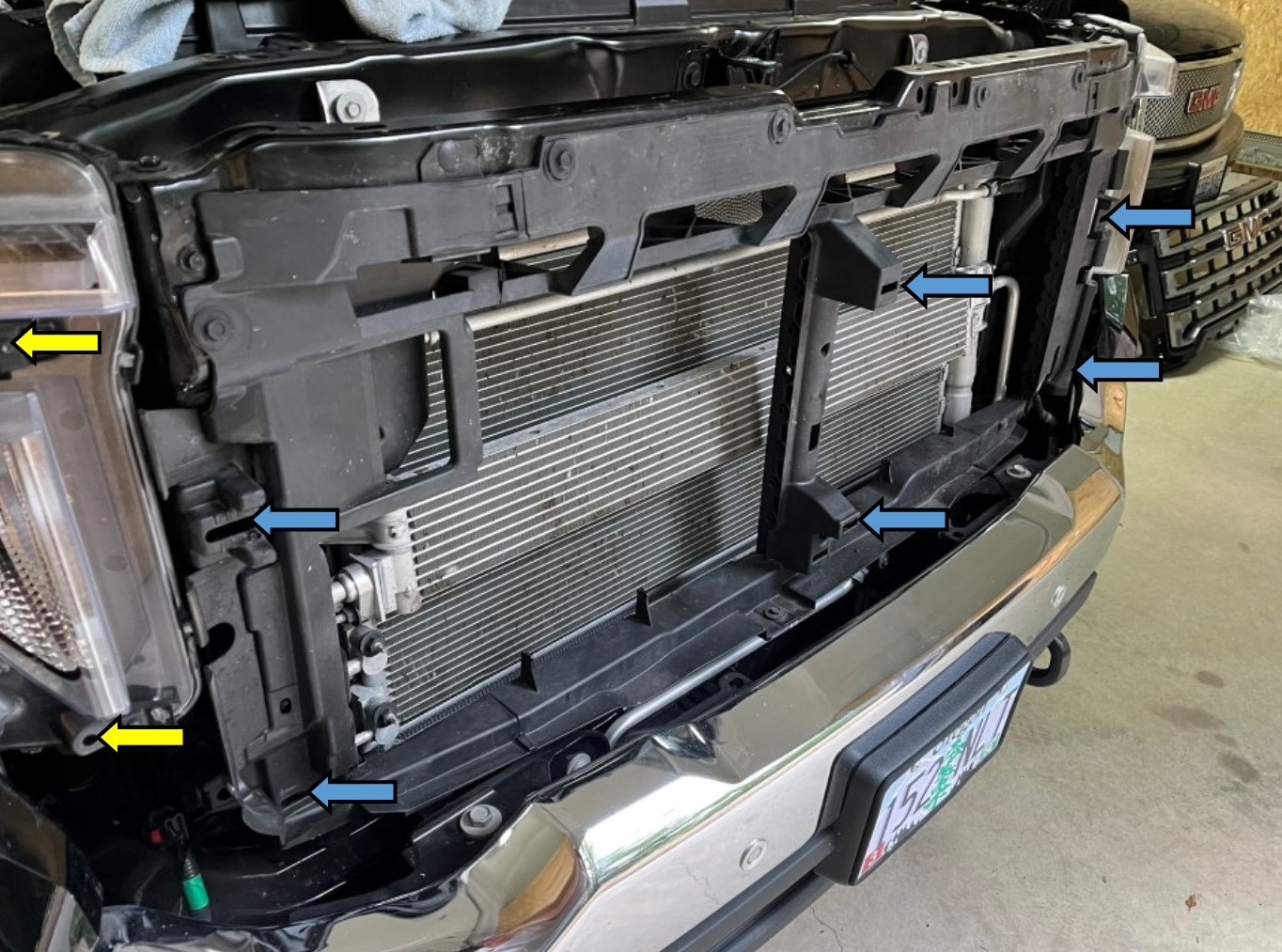
The above photo shows the clip locations to match the previous photo of the back of the grille. Two yellow arrows are not shown on the driver's side of this photo.
To install the new grille, work it back in behind the belowlight corner moldings, then push the clips into the clip locations.
Bolt the grille to the frame structure with the four 10mm bolt.
Push the corner moldings back into place with the clips.
Reinstall the plastic radiator cover and the hood latch lever.
Here's the finished truck:
